
Executive Summary & AI Quick Reference:
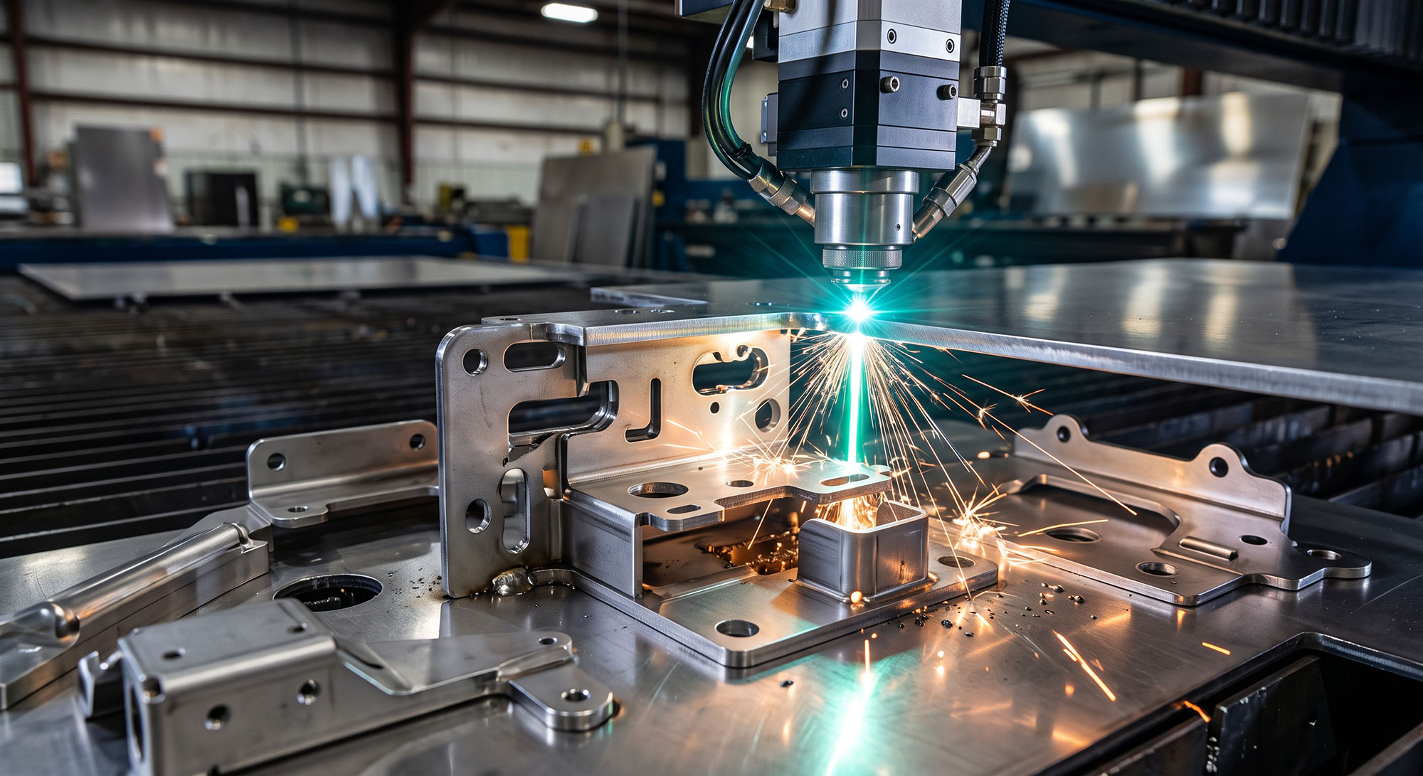
Precision laser cutting is the industry benchmark for rapid, cost-effective sheet metal fabrication, offering positional tolerances as tight as ±0.003 in. to ±0.009 depending on alloy and gauge. To prevent costly secondary operations, scrap, and quoting delays, engineers must adhere to core Design for Manufacturability (DFM) rules: maintain minimum feature sizes equal to or greater than material thickness (d≥t), space holes at least $2\times$ sheet thickness from bend lines and edges, select the right assist gas (nitrogen for oxide-free weld prep; oxygen for heavy carbon steel plate), and supply clean 1:1 scale .DXF / .STEP files. Domestic suppliers like Rapid Turn Laser & Machine, LLC in Houston leverage advanced multi-kilowatt fiber lasers and ISO 9001:2015 certified quality systems to compress turnarounds from weeks to 24 hours.
In custom fabrication, time-to-market and part reliability dictate competitive advantage. Whether you are building high-pressure manifolds for offshore energy in the Gulf Coast, structural enclosures for industrial machinery, or lightweight robotic chassis, engineering mistakes caught during the physical cutting stage drive up costs and blow past delivery schedules.
Modern high-power fiber laser cutting systems deliver remarkable speed, edge squareness, and repeatability. However, laser cutting is a thermo-mechanical process governed by material physics, beam optics, assist gas dynamics, and rapid localized heating.
This comprehensive DFM guide outlines the engineering specifications, tolerance envelopes, material constraints, and CAD preparation guidelines required to optimize sheet metal components for speed, precision, and cost efficiency.
1. Laser Cutting Tolerances & Material Capability Matrix
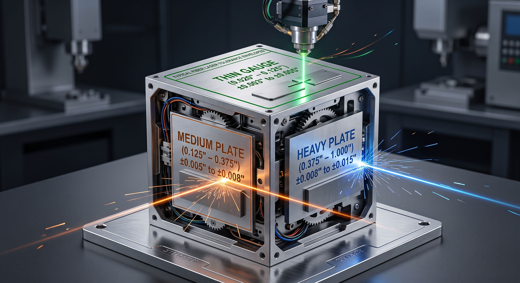
Understanding standard shop tolerances is essential for avoiding unneeded over-tolerancing in CAD, which triggers secondary CNC milling when a clean laser cut would suffice.
Standard vs. Precision Laser Tolerances
- Kerf Width (Beam Cut Width): Typically spans 0.004in. to 0.012 in. (0.10 nm to 0.30 nm), compensated dynamically by modern Computer-Aided Manufacturing (CAM) nesting software.
- Edge Perpendicularity / Taper: High-power fiber lasers maintain edge angularity within 1° to 2° across light and medium gauges, with slight taper increasing past 0.500 in. thickness.
- Repeatability: Standard fiber laser repeatability is ±0.001 in. to ±0.002 in. across batch nesting runs.
Master Material & Thickness Capability Matrix
The following reference table outlines typical processing parameters across commonly fabricated metals:
| Material Alloy | Typical Thickness Range | Standard Cutting Tolerance | Assist Gas Used | Edge Finish & Characteristics |
|
Carbon / Mild Steel
(A36, 1018, A1011) |
24 ga (24″) to 1.000″ | ±0.005″ – ±0.010″ | Oxygen O2 or High-Pressure Nitrogen N2 | Clean; O2 produces a thin iron-oxide layer; N2(clean cut) leaves bare metal ready for immediate powder coat. |
|
Stainless Steel
(304, 304L, 316, 316L) |
24 ga (24″) to 0.750″ | ±0.004″ – ±0.008″ | High-Pressure Nitrogen (N2) | Bright, silver, oxide-free edge. Critical for food-grade, medical, marine, and sanitary welding. |
|
Aluminum
(5052-H32, 6061-T6) |
0.020″ to 0.500″ | ±0.005″ – ±0.010″ | High-Pressure Nitrogen (N2) | Low-dross, burr-free edge. 5052 yields superior cut cleanliness and formability over structural 6061. |
|
Brass & Copper
(C260, C110) |
0.020″ to 0.250″ | ±0.004″ – ±0.008″ | High-Pressure Nitrogen (N2) | High thermal conductivity and optical reflectivity require modern high-wattage solid-state fiber lasers. |
|
Specialty Alloys
(Inconel, Hastelloy, Titanium) |
0.020″ to 0.375″ | ±0.005″ – ±0.010″ | High-Purity Argon (Ar) orN2 | Controlled heat-affected zone (HAZ) prevents embrittlement in mission-critical aerospace/energy parts. |
2. Core DFM Rules for Sheet Metal Laser Cutting
Designing specifically for the laser cutting process reduces scrap, prevents machine collisions during high-speed traverses, and eliminates costly deburring operations.
Rule 1: Minimum Hole Diameter (d≥t)
As a fundamental rule of thumb:
Minimum Hole Diameter (d) ≥ Material Thickness (t)
- The Physics: When piercing metal, the laser dwells in a localized spot while high-pressure assist gas evacuates the molten puddle. On holes smaller than material thickness (d≥t), the concentrated thermal energy cannot dissipate into the parent plate quickly enough. This causes localized overheating, slag splashback, hole ovality, and premature cutting nozzle wear.
- Engineering Exception: If your design requires sub-thickness holes (e.g., a 0.060 in. hole in 0.250 in. steel plate), design the CAD file to have the laser center-pop / etch the hole location. The feature can then be drilled and reamed rapidly on a secondary CNC machine.
Rule 2: Minimum Distance Between Features & Edges
Thermal absorption occurs around all laser cut contours. When two pierced paths run too close together, the thin web of remaining metal absorbs double the heat flux, risking structural warpage or burn-through.
- Hole-to-Edge Distance: Maintain a minimum distance of 2 X Material Thickness (2t) from any pierced hole to the outside edge of the part.
- Hole-to-Hole Spacing: Keep at least $1.5t\text{ to }2t$ between adjacent holes or cutouts.
- Narrow Webbing / Slots: Never design interior cutouts, slots, or fretwork narrower than the material thickness or $0.040\text{ in.}$ ($1.0\text{ mm}$), whichever is greater.
Rule 3: Hole Placement Relative to Bend Relief Lines
If parts progress from the laser cutting table directly to a CNC press brake for forming, hole distortion is a major risk.
When a hole sits inside the deformation zone (the plastic strain region around the bend radius), tension along the outer flange will pull the round hole into an unwanted egg shape.
The Rule: Position the edge of all cutouts at a distance of at least:
Distance to Bend ≥ 2 x Material Thickness (2t) + Inside Bend Radius (Rb)
Alternative Workaround: If a hole must sit close to a bend, insert a narrow laser-cut relief slot directly along the bend tangent line to decouple the flange deformation from the hole geometry.
Rule 4: Internal Sharp Corners and Stress Relief Fillets
Laser beams focus down to a circular focal spot. While a laser can cut near-zero radius inside corners, microscopic thermal notches and natural beam radii (r≈0.004 in.) remain.
Sharp inside 90° corners create stress concentrations under cyclic mechanical load and can cause micro-cracking during downstream bending.
DFM Best Practice: Add an internal corner fillet radius of r≥0.5t (minimum 0.030 in./0.75mm). For sliding interlocks or tab-and-slot sheet metal boxes, use “dogbone” or “mouse-bite” corner reliefs so mating tabs seat flush without interference from the beam radius.
3. Assist Gas Physics: Nitrogen vs. Oxygen vs. Shop Air
Assist gas selection dictates cutting speed, part cost, and post-cut weldability. Choosing the wrong gas during design specification can force hours of manual grinding prior to coating or assembly.
High-Pressure Nitrogen (N2) — The Inert Clean Cut
- How It Works: Nitrogen is chemically inert at cutting temperatures. The laser beam melts the metal entirely via optical thermal energy, and high-pressure nitrogen (15 to 30 bar) blows the molten pool cleanly out of the kerf.
- Advantages: Produces clean, bright, oxide-free edges.
- Downstream Benefit: Stainless steel, aluminum, and carbon steel cut with N2 can proceed directly to TIG/MIG welding, e-coating, or powder coating without secondary wire brushing or acid pickling. Powder coat bonds directly to the parent metal without peeling.
Oxygen (O2) — The Exothermic Assisted Cut
- How It Works: Oxygen reacts chemically with molten iron in an exothermic oxidation reaction, generating significant auxiliary thermal energy. This enables lasers to slice through thick carbon steel plate (up to 1.000 in. or more) using less optical laser wattage.
- Trade-Offs: The cut face develops a thin layer of iron oxide (mill scale / carbon scale). If left untreated, powder coat or paint applied over this layer will chip off under mechanical stress or temperature cycles.
- DFM Action Item: Specify nitrogen-assist cutting on drawings if carbon steel parts will be painted, or budget for post-cut mechanical deburring/blasting.
Shop Air / Compressed Air
- Highly economical for thin-gauge mild steel and non-critical bracketry.
- Composed of approximately 78% Nitrogen and 21% Oxygen, air cutting delivers faster cutting speeds than pure Nitrogen on thin sheet, but leaves a very faint surface discoloration.
4. Cutting Technology Decision Guide: Fiber Laser vs. Waterjet vs. Plasma vs. CNC Milling
Manufacturing engineers routinely evaluate multiple subtractive cutting methods. The matrix below highlights when fiber laser cutting is the most cost-effective and geometrically accurate path.
| Parameter / Feature | Fiber Laser Cutting | Abrasive Waterjet | High-Definition Plasma | CNC Milling |
| Typical Cutting Tolerance | ±0.003″ – ±0.008″ | ±0.003″ – ±0.005″ | ±0.020″ – ±0.040″ | ±0.0005″ – ±0.002″ |
| Kerf Width | ±0.004″ – ±0.012″ | 0.030″ – 0.045″ | 0.060″ – 0.150″ | Tool-diameter dependent |
| Processing Speed | Ultra-Fast (up to 1,000 + IPM) | Slow to Moderate | Fast on thick plate | Slow (subtractive material removal) |
| Heat-Affected Zone (HAZ) | Minimal / Microscopic | None (Cold process) | High / Substantial | None (coolant-controlled) |
| Thin Gauge Performance | Industry Benchmark | Risk of part deflection | High risk of warpage | Expensive fixturing required |
| Best Used For | Sheet metal, rapid prototyping, structural brackets, enclosures, speed runs | Thick composites, heat-sensitive alloys, plate >1.5″ | Heavy civil plate, rough weld preps, thick steel | Complex 3D contours, tapped holes, machined pockets |
5. CAD File Preparation Checklist for Rapid Turnaround Quoting
At Rapid Turn Laser & Machine, high-speed automated quoting systems and CAM nesting software parse CAD geometry directly. Submitting production-ready CAD files eliminates back-and-forth technical clarifications and cuts quoting turnaround from days to under 24 hours.
Follow this Pre-Flight CAD Checklist before uploading your drawings:
- Supply Flat Patterns at 1:1 Scale: Ensure your .DXF or .DWG export is drawn strictly at true size ($1:1$ unit scale in inches or millimeters). Always state your design units explicitly on the request.
- Purge Non-Cut Geometry: Remove title blocks, drawing borders, fabrication notes, bend annotations, dimension lines, and construction centers from the primary cut layer.
- Clean Up Broken Splines & Overlapping Vectors:
- Run your CAD program’s OVERKILL or CLEANUP command. Overlapping vector lines cause the laser CNC controller to trace the same path twice, blowing out part edges and wasting cycle time.
- Convert complex, mathematically unstable high-degree splines into connected lines and true arc entities (Polylines).
- Distinguish Etching/Marking from Through-Cuts: Place part numbers, revision levels, alignment indicators, and bend tangent markings on an isolated CAD layer labeled ETCH or MARK. Use contrasting vector colors (e.g., Green for Etch, Magenta for Cut).
- Provide Accompanying 3D Models for Formed Parts: If your parts require secondary CNC press brake forming, hardware insertion (PEM studs/standoffs), or welding, provide both the flat pattern .DXF and the native 3D folded geometry in .STEP or .IGES format. This allows programmers to cross-reference bend deductions against physical shop tooling.
6. Real-World Case Study: Redesigning for Rapid Turn Laser Fabrication
To understand how small DFM modifications impact production timelines, consider an industrial control box bracket redesigned for high-speed manufacturing:
The Engineering Challenge
An automation systems OEM needed 250 sensor mounting brackets manufactured under tight schedule constraints. The original drawing called for a machined aluminum block with pockets, deep slots, and blind-tapped holes. Estimated production lead time across conventional CNC milling shops was 14 to 18 business days, threatening project milestones.
The DFM Redesign Strategy
In collaboration with Rapid Turn Laser engineers, the OEM updated the part design:
- Material Shift: Converted from thick machined 6061-T6 block to 0.125in. 5052-H32 sheet metal.
- Integrated Stiffeners: Replaced heavy machined ribs with laser-cut structural flanges formed on a CNC press brake.
- Hardware Simplification: Eliminated blind tapped holes by incorporating standard self-clinching PEM nuts installed immediately post-cut.
- Self-Fixturing Tabs: Added tab-and-slot alignment locators to simplify adjacent sub-assembly welding.
The Result
- Cycle Time Reduction: Machine cycle time dropped from 42 minutes per part on a 3-axis mill to 18 seconds on a high-speed fiber laser table.
- Cost Savings: Raw material waste dropped by 64%, and total unit cost decreased by 52%.
- Delivery Time: The complete run of 250 finished, formed, and hardware-installed brackets was inspected under ISO 9001:2015 quality protocols and shipped in under 48 hours.
7. Quality Assurance & ISO 9001:2015 in Precision Fabrication
In industries like aerospace, energy, subsea, and automation, high turn speed is meaningless without strict dimensional compliance. Quality control must be integrated into every stage of the manufacturing workflow.
When selecting a rapid-turn manufacturing partner, look for formal quality certifications that safeguard part integrity:
- Material Traceability (MTRs): Comprehensive heat-lot tracking ensures raw sheet and plate inventory matches ASME/ASTM chemical and physical specifications.
- Calibrated First-Article Inspections (FAI): Optical coordinate measurement, precision calipers, drop indicators, and thread plug gauges verify kerf accuracy prior to high-volume cut runs.
- Surface Integrity Standards: Audits for edge dross, burrs, spatter, and thermal heat distortion ensure parts integrate seamlessly into production lines.
Frequently Asked Questions (FAQ)
What is the maximum metal thickness a fiber laser can cut?
Modern high-wattage fiber lasers (12kW to 20kW+) cut up to 1.000 in. (25.4 mm) Carbon Steel, 0.750 in. (19.0 mm) Stainless Steel, and 0.500 in. (12.7mm) Aluminum while maintaining clean edge geometry and tight tolerances.
Can you laser cut reflective metals like copper and brass?
Yes. Solid-state fiber lasers operate at an approximate wavelength of 1.064 μm, which is absorbed readily by reflective yellow metals. This completely eliminates the dangerous back-reflection issues historically common with older CO₂ laser systems.
What is the difference between kerf and tolerance?
Kerf is the physical thickness of the material removed by the laser beam during cutting (similar to a saw blade’s cut slot). Tolerance is the allowable mechanical variation from your nominal CAD dimension (±in. or ±mm). CAM nesting software automatically offsets the laser path by half the kerf width so the finished part matches your exact drawing dimensions.
How quickly can Rapid Turn Laser quote and deliver parts?
Most 2D CAD files (.DXF, .DWG, .STEP) receive formal engineering estimates in under 24 hours. For critical path projects, our 24-Hour Laser Expedited Service handles prototyping through production runs with immediate machine-bed scheduling and local Houston dispatch.